Page 1 of 4
Field map implementation
Posted: Mon 5 Apr 2021 14:57
by Vyacheslav
Dear Didier,
please look at my project with field maps usage .
It was obtained the next program message when I run my project.
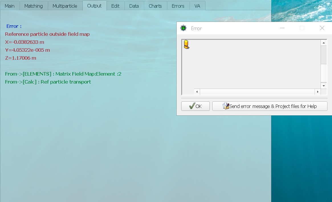
- message.jpg (78.79 KiB) Viewed 11474 times
Unfortunately it is not clear for me how describe element locations if its field maps does not overlap.
What is wrong and what will be right in my case?
Also I cannot understand description of the Quad field file of the program example in contrast to Dipole one as it is illustrated below.
- Qpole.jpg (330.11 KiB) Viewed 11474 times
vs
- dipole.jpg (48.58 KiB) Viewed 11474 times
Is the file structure for Quad description is the same as for Dipole?
Re: Field map implementation
Posted: Mon 5 Apr 2021 15:46
by Didier
Dear Vyacheslav,
I have no way of knowing what your different field maps contain, so I proceed as follows and this method can help you in the future for simple cases. For more complicated things you have to do the work of drawing the expected central trajectory and putting the SUPERPOSED_MAP commands according to the different position of the elements. So, for your case, I remove all the SUPERPOSE_MAP and SUPERPOSE_MAP_OUT commands and I get the following path:
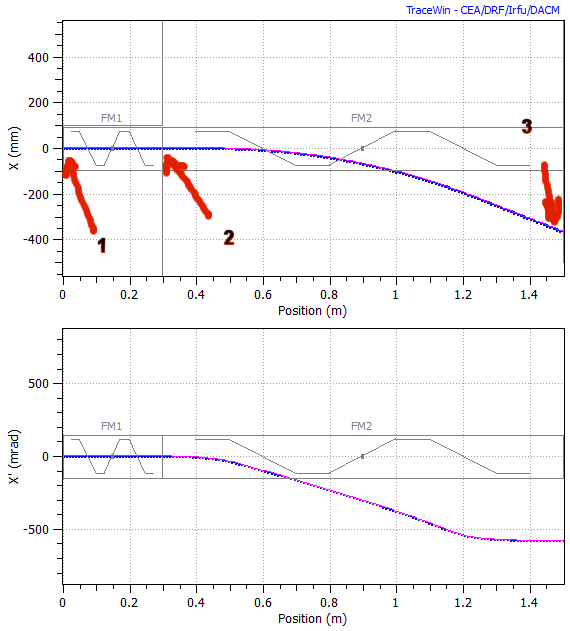
- trajectory.png (21.76 KiB) Viewed 11471 times
Point (1) gives me the coordinates of the input position of the quad, so the first SUPERPOSED_MAP. Point (2) gives me the input coordinates of the dipole, so the second SUPERPOSED_MAP. Finally, the third point (3) gives me the expected output coordinates, so the SUPERPOSED_MAP_OUT.
Finally I have this:
DRIFT 0 100 0 0 0
SUPERPOSE_MAP_OUT 1500 -368. 0 0 0 33.25
SUPERPOSE_MAP 0 0 0 0 0 0
FIELD_MAP 70 300 0 100 1.0 0 0 0 QuadT
SUPERPOSE_MAP 300 0 0 0 0 0
FIELD_MAP 0070 1200 0 1000 1.0 0 0 0 dipoleT
DRIFT 0 500 0 0 0
END
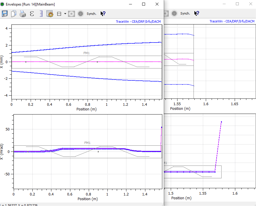
- trajectory2+zoom_sortie.png (34.37 KiB) Viewed 11471 times
It's not perfect and it's normal because my first aproximation (without SUPERPOSE...) the central particle does not pass through the centre of the dipole and the field is therefore different. I just have to adjust Xout and X'out by hand and with :
SUPERPOSE_MAP_OUT 1500 -368.1 0 0 0 30.15
Here I get a central trajectory in the centre of the elements
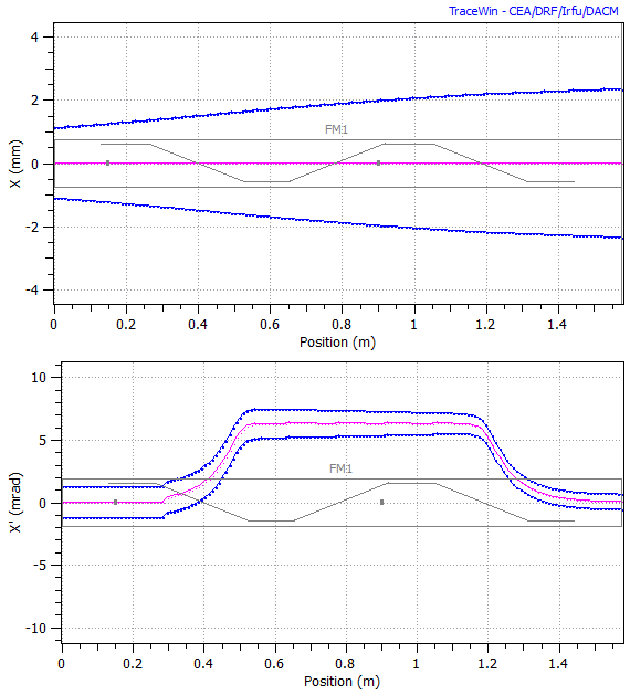
- trajectory_perfect.png (16.06 KiB) Viewed 11471 times
A last point,I think the quad file is in binary format, that's why you can't read it. You can switch to binary or back to ascii using the FIELD_MAP tools. I advise you to switch to binary for the simulations, it is much faster.
Regards,
Didier
Re: Field map implementation
Posted: Tue 6 Apr 2021 22:04
by Vyacheslav
Thanks a lot, dear Didier! I'll try to tune my project.
Re: Field map implementation
Posted: Mon 12 Apr 2021 12:12
by Vyacheslav
Dear Didier,
what shall i do if I use the scheme like as in the picture bellow and which was obtained by "specular reflection" of the BendT and QuadT?
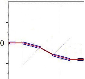
- channel.jpg (12.82 KiB) Viewed 11436 times
Should I export beam passed throughout the first Quad and bend with indicated SUPERPOSE_MAP_OUT parameters and then put the beam in a new channel (second half of the line) with the new SUPERPOSE_MAP_OUT for it?
May be another way exist?
Thanks in advance.
Re: Field map implementation
Posted: Mon 12 Apr 2021 15:11
by Didier
Dear Vyacheslav,
You must have a SUPERPOSE_MAP_OUT at each start of a set of overlapped field_map elements (if they curve the trajectorey).
If your two sections are well separated, then yes 2 superposed_map_outs are needed and moreover it's much easier to implement as you can build your line section after section
Regards,
Didier
Re: Field map implementation
Posted: Wed 14 Apr 2021 09:46
by Vyacheslav
Dear Didier,
can you explain why z-coordinates on the following pictures are different (without and with FIELD_MAP)?
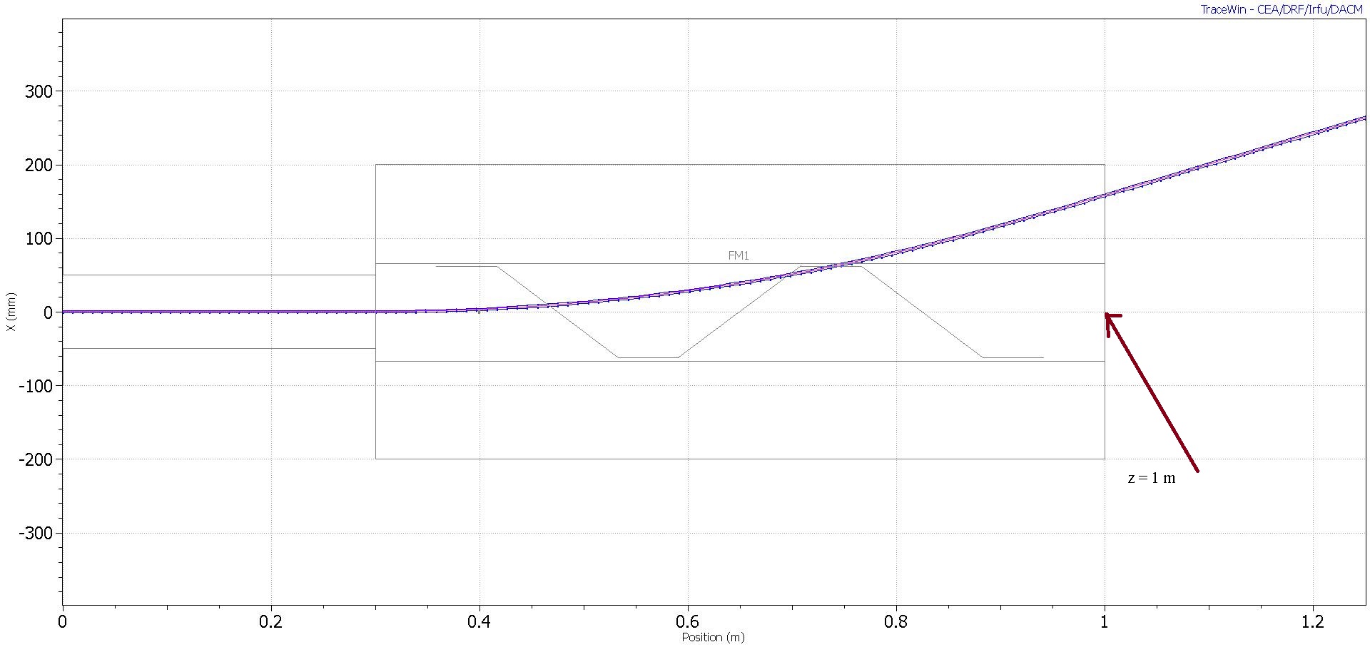
- fm_off.jpg (172.44 KiB) Viewed 11431 times
vs
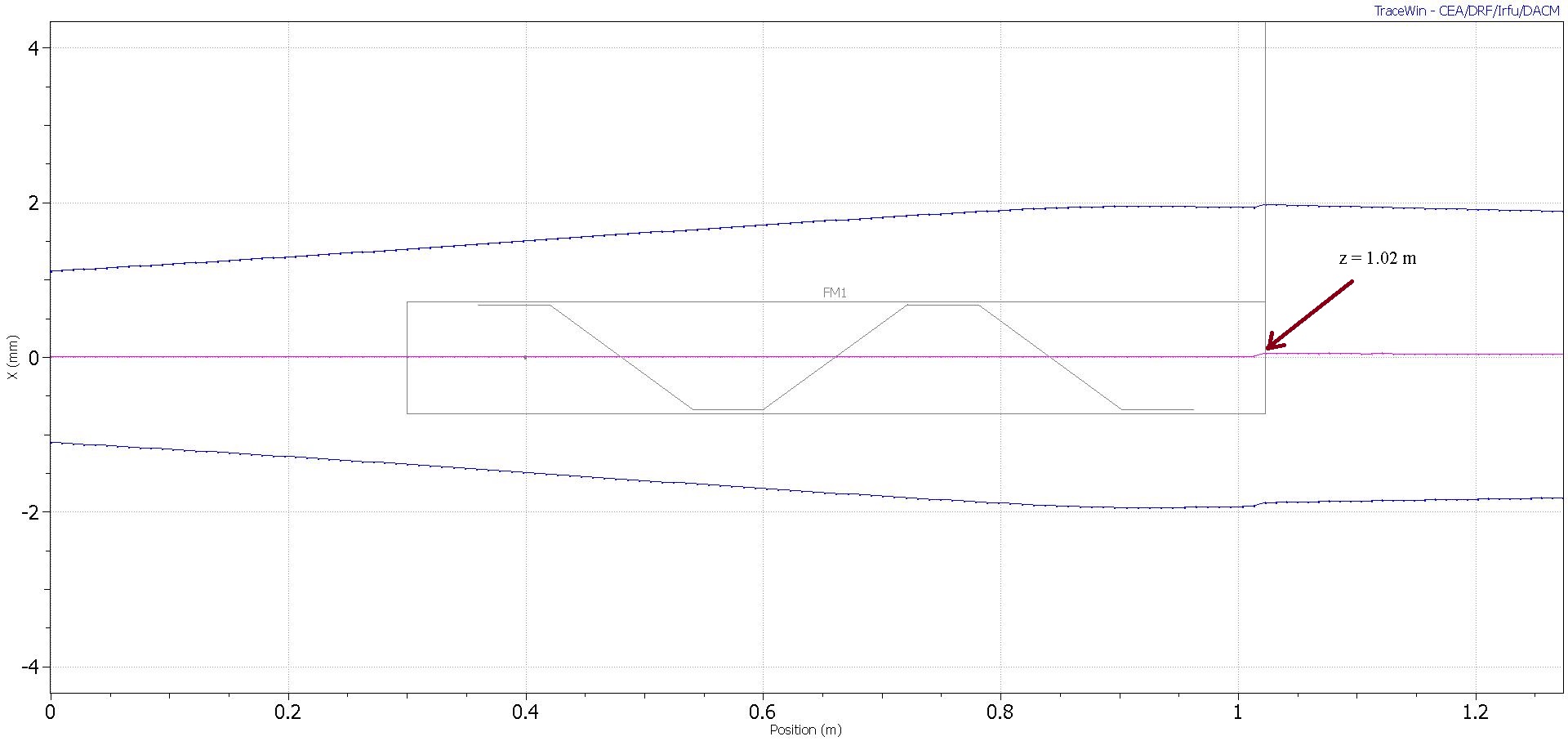
- fm_on.jpg (161.73 KiB) Viewed 11431 times
Project files is attached.
Re: Field map implementation
Posted: Wed 14 Apr 2021 14:51
by npichoff
Dear Vyacheslav,
In the first case (case 1), the reference trajectory is considered going straight through the magnet. 700 mm is the length of the magnet in this direction.
In the second case (case 2), the reference trajectory follows the reference beam trajectory in the magnet. This is an arc of circle of radius R with exit angle teta of about 0.4 rad.
The difference in length between both cases are:
- Case 1: L1 = R*sin(teta) (= 0.7 m)
- Case 2: L2 = R*teta
The ratio is :
L2/L1 = teta/sin(teta) ~ 1.027
This explains why :
D2 = 0.3 m (DRIFT) + L2(=1.027*L1 m) = 1.019 m.
I hope it is clear.
Best regards.
Nicolas.
Re: Field map implementation
Posted: Thu 15 Apr 2021 21:42
by Vyacheslav
Dear Nicolas,
thanks for the answer.
Can you clarify how to use FIELD_MAP of the dipole, which is a sector bend as in this example?
It is length by s-path (not z one) should be equal to R*teta=700 mm. It is needed to compare beam dynamics in meander (square wave) approximation of sector bend with that is for "real" field.
Re: Field map implementation
Posted: Tue 20 Apr 2021 08:46
by Vyacheslav
Dear Didier and Nicolas, one more question.
Why in my case for the first dipole program uses B-field along cartesian z-coordinate and for the second one it uses B-field along the reference trajectory (look at attached pictures)? How does it find them and how put into structure file indication on B-field along the reference trajectory utilization?
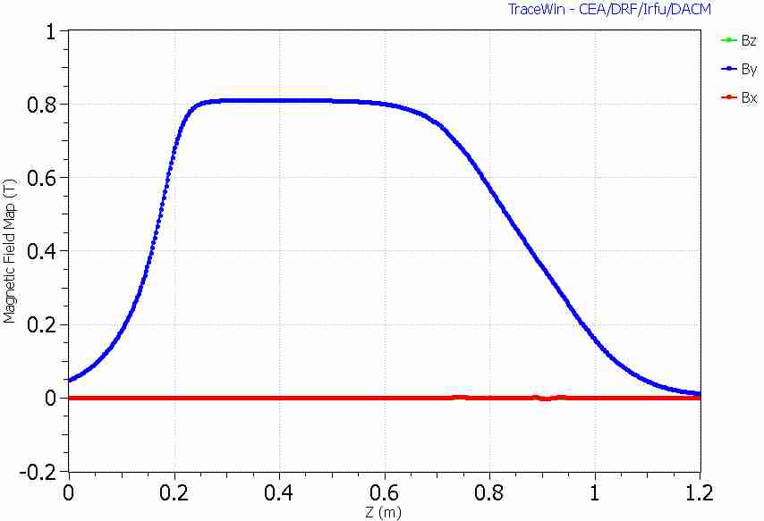
- By_1.jpg (18.72 KiB) Viewed 11394 times
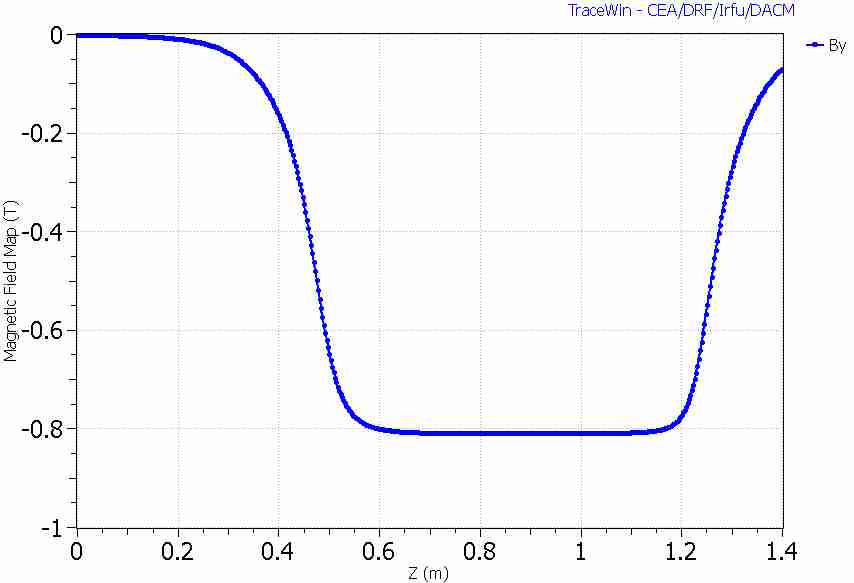
- By_2.jpg (17.65 KiB) Viewed 11394 times
Thanks in advance.
Re: Field map implementation
Posted: Tue 20 Apr 2021 13:30
by npichoff
Dear Vyacheslav,
Please detail how you got these curves, in particular the second curves as field map viewer is not able to plot the field along the reference trajectory.
The basis are :
- the field map is given in a cartesian frame (it can be plotted with field map viewer),
- the magnet is positionned with respect to the upstream linac with its input position and its input angle with SUPERPOSE_MAP command,
- the downstream linac reference trajectory at the exit of the magnet is given by SUPERPOSE_MAP_OUT command,
This is all what is needed to define the position of the accelerator.
- The curved trajectory of the reference particle is calculated in the field map as positionned before.
- In the magnet the particle's position are plotted (envelopes...) in planes orthogonal to this reference trajectory.
- The exit position of the reference particle is compared to the theoretical exit (given by SUPERPOSE_MAP_OUT) in order to calculate the possible misalignment of the beam in the downstream linac.
For better explanation (with drawing), please consult the documentation "Field map with curved reference trajectory".
Best regards.
Nicolas & Didier